What is Hydropower Plant | Components of Hydropower Plant
What Is Hydropower Plant?
A hydropower plant uses the hydraulic energy of water to produce electricity. Hydroelectric power is the name given to the energy produced by this plant. Roughly sixteen percent of the world’s electricity is produced by hydropower. In this article we will try to understand the components of a hydropower plant.
Hydropower Plant Components
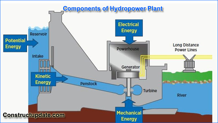
Many different parts work together to power a hydroelectric or hydropower facility. This section provides an overview of the several key parts of a hydroelectric plant.

Storage Reservoir
It is an essential prerequisite for a hydroelectric facility. It helps supply water to the power plant by storing water during the monsoon season and delivering it during the dry season. A reservoir may be man-made or natural.
A lake in the mountains is a natural reservoir; a dam built over a river is an artificial reservoir. Hydropower facilities with low head require a sizable storage reservoir. The difference in runoff during high and low flows establishes the reservoir’s capacity.
Dam
A dam’s two main purposes are to create artificial head and store water by raising a stream’s surface. The most costly and significant part of a hydropower project is a dam.
Stone, concrete, and earth or rock fill are used to build dams. The type and configuration are determined by the location’s geography. One might build a brick dam in a small canyon. An earth dam could be useful in a large valley.
The type of dam chosen depends on a number of factors, including the state of the foundation, the accessibility of local transportation and materials, the frequency of earthquakes, and other hazards.
Forebay
A hydroelectric plant’s forebay is a basin where water is momentarily held before entering the intake chamber. The amount of water required in that location determines how much water is stored in the forebay. When there is less of a load demand in the intake, this is also used.
We are aware that reservoirs are constructed over rivers to hold water, and that penstocks can transport the water held on the dam’s upstream side to the power plant. Here, the reservoir serves as the forebay.
Spillway
The purpose of the spillway is to serve as a safety valve. The reservoir directs the overflow water to the downstream side when it fills up, which typically occurs during floods.
Usually constructed of concrete, these feature metal control gates to regulate the water discharge holes. By adjusting how much the gates are opened to keep the reservoir’s water level stable, the headwater’s outflow to the tailrace may be controlled.
Intake Structure
Between the penstock and forebay is a chain that makes up the intake structure. It travels to the penstock after gathering water from the forebay.
It has a significant function in power plants. Water from the river enters the reservoir or forebay. As a result, there is a lot of dirt and rubbish in the water.
Trash racks are located near the penstock’s entrance and are part of the intake structure.
Steel rods are used to make the trash racks. It keeps the nozzle and turbine blades from suffering significant damage. Steel rods are positioned in trash racks 10 to 30 centimeters apart.
During the cold season, trash racks are heated to prevent ice pebbles from colliding with turbine blades. The ice boulders near the penstock’s entrance melted because of the heat in the trash racks. After a set amount of time, the trash racks need to be cleaned. Additionally, the trash racks are cleaned using racks and trolly arrangements.
Penstock
Large, sloping pipelines called penstocks are used to move water from an intake structure to the turbines. The main purpose of the penstock is to deliver pressurized water to a hydraulic turbine’s entrance.
Penstocks are usually made of steel or reinforced concrete. For each turbine, a separate penstock is used if the length is small; if the length is considerable, a single, large penstock that is later separated into branches is employed.
Penstocks are rounded in shape to equalize pressure distribution and lessen circumferential stress concentrations. The circular cross-section of the penstock also lessens the possibility of scaling, which is more typical for square cross-sections.
The penstock canal may be subterranean or exposed to the elements, depending on the climate and topography.
Surge Chamber
A surge chamber, sometimes referred to as a surge tank, is an open-topped, cylindrical tank used to regulate the pressure inside the penstock. It is situated as close to the powerhouse as feasible and is connected to the penstock.
The water level in the surge tank rises when the powerhouse rejects the penstock’s water load, allowing the penstock’s pressure to be regulated.
In a similar vein, the surge tank lowers the water level in the powerhouse by increasing the water flow into it during periods of high demand. The surge tank’s water level stays constant when the powerhouse discharge does as well.
Hydraulic Turbines and Generators
By connecting the shaft of the turbine to the generator, hydraulic energy is converted into mechanical energy, which is subsequently converted into electrical energy using a hydraulic turbine.
In this case, the generator generates electricity by rotating the central shaft in response to high-pressure water from the penstock striking the circular blades or runner.
The generator is powered by the mechanical energy produced by the turbine. It is directly connected to the turbine’s shaft. Electric power is produced by the generator. Essentially, there are two kinds of hydraulic turbines:
- Impulse turbine
- Reaction turbine
The hydroelectric plant’s generator serves as the primary energy conversion source. Generators are devices that transform mechanical energy—mostly hydroelectricity—from the shaft movement of a turbine into electrical energy.
An armature, a set of coils, and large magnets make up a generator. A current flows through the coils as a result of the generator’s armature rotating, which modifies the magnetic flux.
After the current is sent to a step-up transformer, it is directed through electrical cables. Usually, the current output of the generator is expressed in bigger terms like megawatts and kilowatts.
Draft Tube
A lengthy tube having a diverging cross-sectional area is called a draft tube. Transporting the discharge water from the turbine to the tailrace is the main use of a draft tube in a hydroelectric plant.
The draft tube converts energy by merely applying Bernoulli’s theorem. The turbine operates at a head equal to the headrace water level above the runner outlet in the event that there is no draft tube and the water flows out of the turbine exit without restriction.
The working head is elevated by the runner outlet’s height above the tailrace by adding a draft tube. A negative pressure head forms close to the runner’s exit as a result. As a result, the turbine’s head can remain in place when it is positioned above the tailrace.
Tailrace
Water that leaves the turbine is collected in a tailrace, which is a type of water collection device. The water’s kinetic energy is converted into pressure energy via the draft tube’s divergence. A tailrace is the term used to describe the water flow from turbines to the stream.
The power plant should be positioned as close to the stream as possible. If it is situated far from the stream, though, a canal for transferring water into the stream needs to be constructed.
If not, the water flow could damage the plant in a number of ways, such as reduced turbine performance, cavitation, damage to the turbine blades, and more. Water should be able to exit the tailrace easily, and once it leaves the turbine, the water jet should also be able to move freely.


